

Universal Fitment Harness Installation Instructions
Harness connections -note some will not apply to your harness
Before beginning please be sure you have a proper engine to battery ground, if you do not their is a chance the engine harness may be damaged when starter is en-gauged due to the harness acting like a ground strap and over loading the small engine grounds in harness and melting/burning harness.
The battery lead needs to be connected to the battery + terminal, also an easy solution to tucked battery locations would be to attach the harness to the starter battery + post as you should already have a nice large battery lead running to the starter-and the leads are long enough to reach the starter on most every harness.
Fuel pump + needs to power up your fuel pump. Simply unhook the oem wires/cover the ends for safety, and extend new lead to the fuel pump(s) - some cabbies have lift pumps so be sure to power both pumps!!!
Body ground needs to simply be attached to a clean metal surface on car with a nut/bolt or self tapper screw.
The trigger lead is the most difficult lead for most. it needs to be attached to a power source that is 12V when the key is turned to on position AND stay 12v while the key is in crank position. A sure fire method is to attach to the smaller black wire on most all mk1-mk3 ignition switches. Its easy to test to make sure the lead is good, just hook a test light to the suspected trigger lead you want to use. Turn the ignition key on- light should glow. Now turn the key to start/crank and the light needs to keep glowing....if it goes out it will not work and find another. if all else fails a small toggle switch from the battery plus to the trigger lead will work-switch on will make ecu alive, switch off would shut off motor.
The coolant gauge lead uses the factory sender and hooks to the oem lead in your cluster harness to make the gauge read, in some cases it may be incorrect so verify operating temps on gauge using a scan tool and compare ecu coolant temp to actual gauge. Resistors can be added to lead to bring reading down on gauge as some mkiv senders read "high" on older clusters.
The oil pressure light is a simple dummy light circuit. The lead is grounded when engine is off, and goes open circuit when engine starts.....on a mkiv the sender is reverse function. neither are actual gauge leads, just for dummy light.
The oem tac lead will need a signal booster for older mk1/mk2 clusters and can be supplied when applicable. On mkii and up clusters the oem tac lead generally will work proper. On vr6 with 4 cyl cluster a full tac adaptor must be used and can be supplied when applicable.
Glow plug light is a ground switch supplied by ecu for cluster function of glow plug bulb.
Two step lead if present will be a twisted loop at the ecu connector. When this wire is cut and “not connected to itself” and the throttle is depressed beyond 80% two step will bang and pop- use at your engine/exhaust own risk- not responsible for any damage resulting from “explosions”!!
For no start conditions first things to check:
Verify the ecu will communicate with a scan tool, note that obd1 ecu’s will ONLY work on a VCDS scanner.
With obd1 ecu’s the fuel pump should prime for 1 second when key is first turned on, if it does not their is a very good chance the ecu is bad….very common on obd1.
On odb2 ecus the fuel pump will only prime once and then not again for some time with key cycles, this is normal.
Check for spark while cranking, if you have no spark, that’s not good…..next check to see ecu understands the motor is rotating. To do this have a friend help or use a test light. First method is to pull the fuel line feed, put it in a bottle and crank motor, fuel pump should fire up while your cranking the motor over….if it does the ecu is seeing engine rotation, this is good. Second method is put the test light on the fuel pump + lead and make sure the light glows while cranking.
Next temporarily run the trigger to the battery plus and retest above steps, if anything changes then you need to find a proper trigger lead power source as stated in above description of trigger lead.
Next if its OBD2 you should hear the throttle body hum with key on, this means ecu is alive!
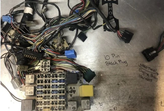
Late Westy fuse panel: 10 pin black plug
1 black ignition power/Trigger wire
2 blue/yellow coolant temp
3 green/blue reverse light switch power
4 black/green- do not use, CIS wiring
5 black/yellow trigger for cluster glow plug light-diesel
6 red/black tachometer
7 red/black (heavy gauge lead) starter solenoid
8 blue/black low oil pressure light
9 Black reverse light switch power return
10 green/green aux oil gauge lead-NO US
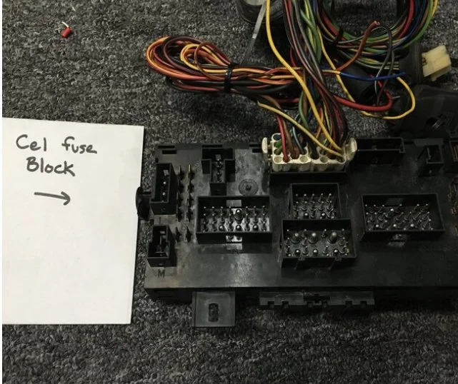
CE1 Fuse block pinout- D plug, white in color
D2 black- trigger wire (fuse 17)
D1 blue/black low oil pressure light cluster
D21 yellow high oil pressure switch (ground to chassis if not using sender on motor)
D29 yellow/red Coolant temperature cluster
D26 red/black tachometer cluster
D9 green/yellow,12 green ,17 green/black ,20 black/grey ,22 brown: All Wiper motor
D22 Brown (wiper &) Fuse box Ground to chassis
D16 black/red & D19 black/blue Rever light switch
D24 red/black Starter solenoid


ABA Tips and References
A common problem when swapping an ABA is timing the motor. When this is done improper you may either get a no start condition or a possible cam position sensor code. This code is indicative to a distributor that while being close enough in time to run is not timed proper to the crank in relation to the sensor in the distributor. The following pictures display the proper orientation of all components when at TDC.
Ignition firing order of an ABA is 1,3,4,2 counter clockwise starting with the post on distributor cap the rotor button is pointing to when motor is at TDC.
Fuel rail connections are noted in pictures below as well.


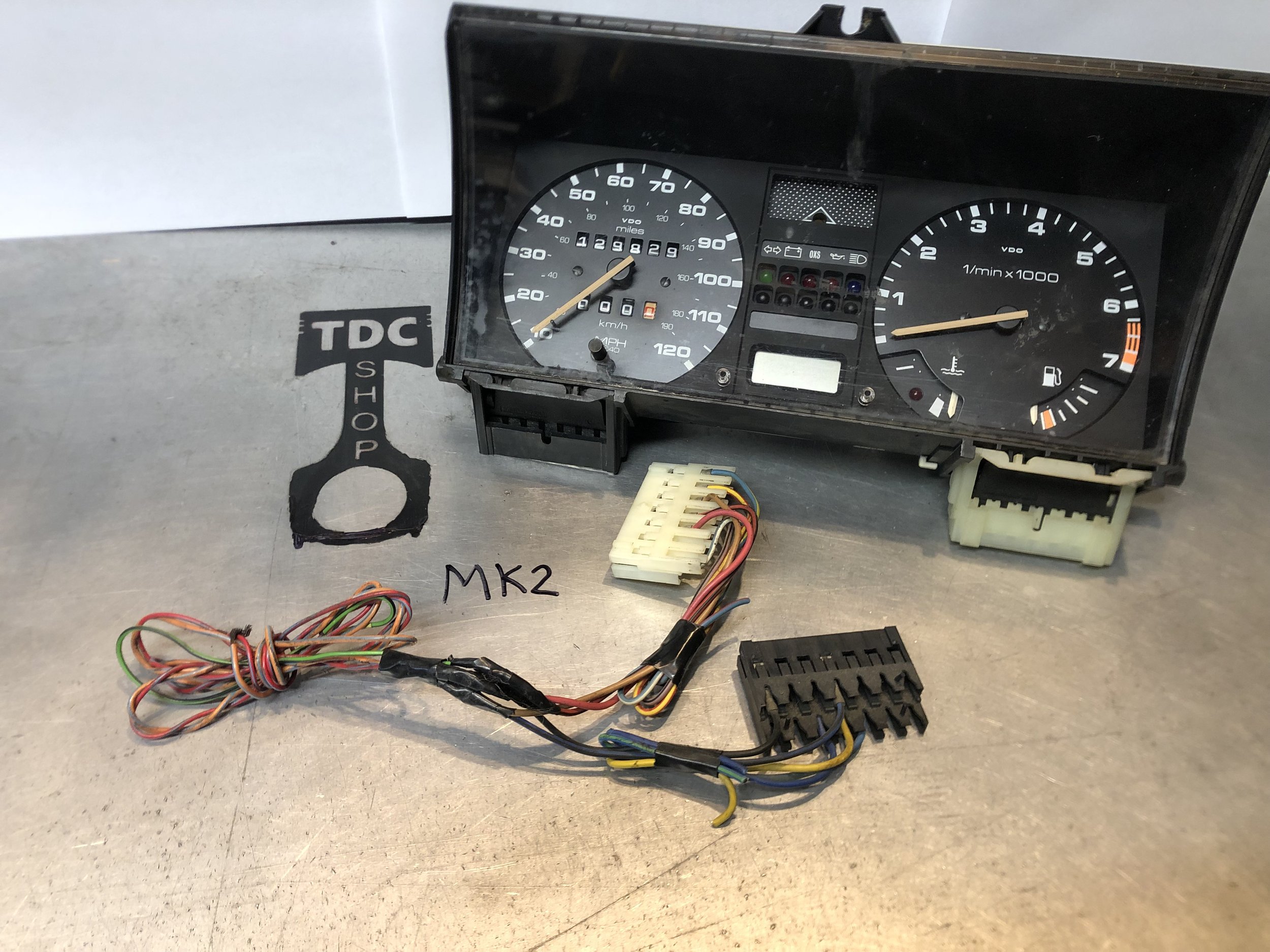
Late Westy - MK3 Cluster reference pictures for install


Late Westy Cluster
1 empty
2 Low coolant ( not always their) yellow/brown
3 battery red/grey
4 fuel gauge lilac/grey
5 Tachometer red/black
6 dash lights grey/blue
7 ground brown
8 Generally empty- upshift light circuit
9 Turn signal (- signal turns them on) green/black
10 High beam (12V trigger) white
11 Alternator battery light blue
12 Brake light (- input) grey/green
13 Ignition power black
14 Sat belt (- input) white/violet
15 Yellow upshift light circuit.
16 Low oil pressure light blue/black
17 Glow plug light (- trigger) black/yellow
18 Temp gauge Blue/yellow
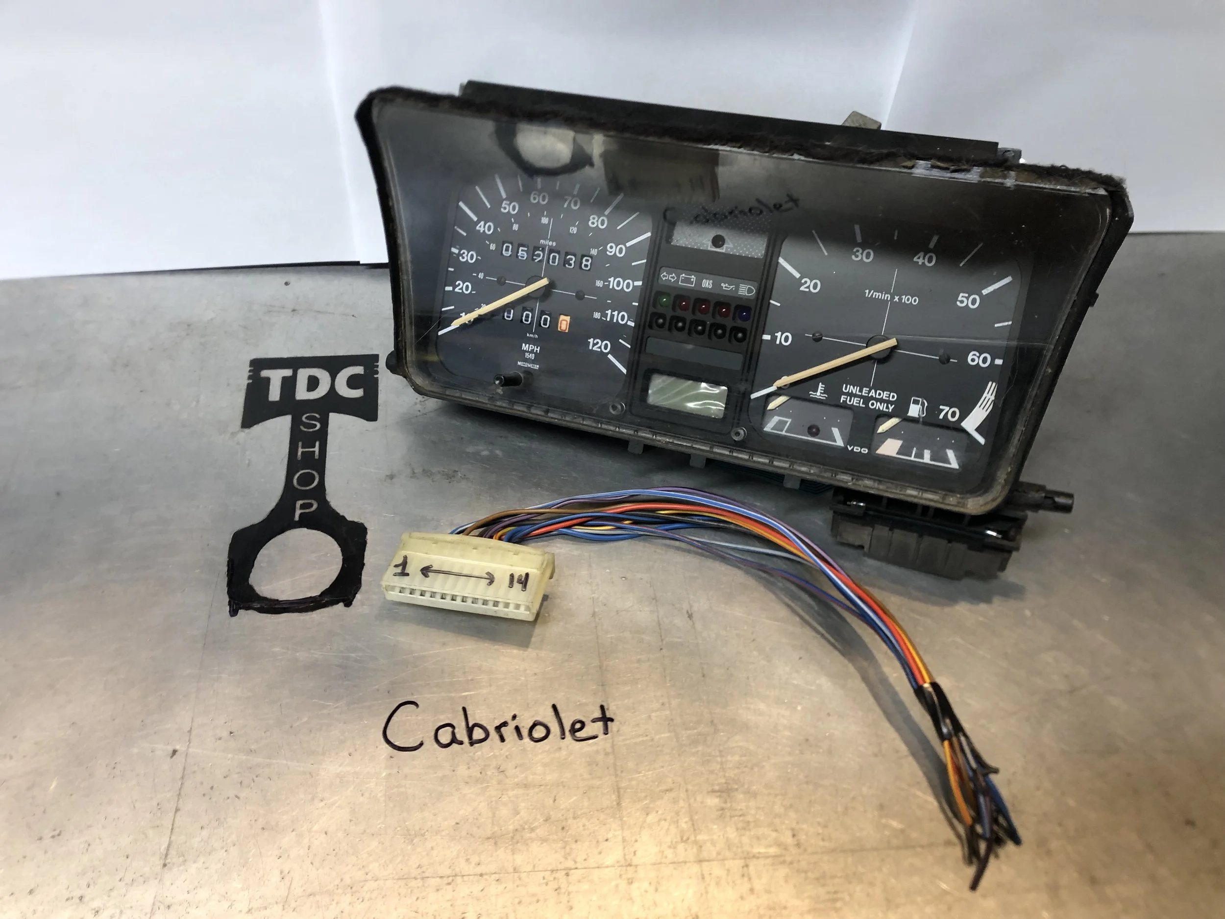
Cabriolet Cluster
1 Dash light power grey/blue
2 Ground brown
3 Fuel gauge purple/black
4 Temp gauge yellow/red
5 Tac lead red/black
6 battery power red
7 High beam light whit/blue
8 Empty
9 Low oil switch 1.8bar blue/black
10 Oxy light blue/green
11 Oil light .3bar Yellow
12 Alternator battery light blue
13 Turn indicator blue/red
14 Black ignition power
T7C (black)
1 multi switch grey/red
2 speed sensor output from speedo head blue/white
3 empty
4 low oil pressure switch input .3 bar blue/black
5 empty
6 empty
7 ignition power yellow/red
T7a(black)
1 empty
2 multi switch green/glack
3oxygen sensor light trigger brown/black
4 hi oil pressure switch input grey/white
5 alternator light trigger blue
6 empty
7 empty
T7(white)
1 Hi beam light trigger input white
2 Outside air temp input black
3 multi switch grey/yellow
4 outside air temp input ground brown
5 fuel tank level purple/black
6 dash light input grey/blue
7 turn signal trigger input green/black
T7b(white)
1 upshift light trigger violet/black
2 oil temp input green/black
3 battery power to cluster grey/blue
4 tachometer input green/blue
5 brown ground
6 coolant temp gauge input blue/yellow
7 upshift light trigger blue/white